Specification
Belt Types
Select the belt construction first, then use its own drawing and enquiry form. Each section below brings together the mesh dimensions, edge details and information required to specify a new belt or identify an existing one.

Standard Chain Link without Chain Edge Drive
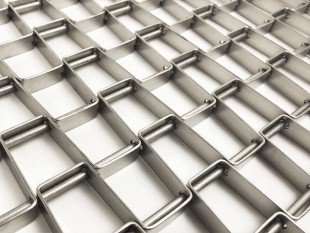
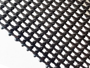
Interwoven coils form an open mesh without reinforcing rods through every coil connection. This simple construction suits selected low-load drying and cooling duties. Panel connector wires may still be used where opposite-hand sections are joined.
View dimensions & edge options
|

Rod Reinforced Chain Link without Chain Edge Drive
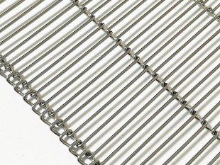
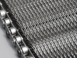
Cross rods pass through the interconnecting spiral wires to improve strength and lateral stability compared with a comparable unreinforced mesh. Allowable load depends on the wire sizes, pitches, material, temperature and support arrangement.
View dimensions & edge options
|

Duplex Rod Reinforced Chain Link without Chain Edge Drive
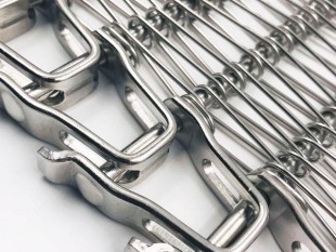
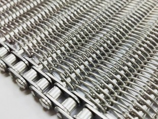
Twin intermeshing coils at each position provide a denser mesh than a comparable single-coil design. Cross rods reinforce the assembly. Select this version where additional product support or load capacity is required, while checking the resulting open area and flexibility.
View dimensions & edge options
|

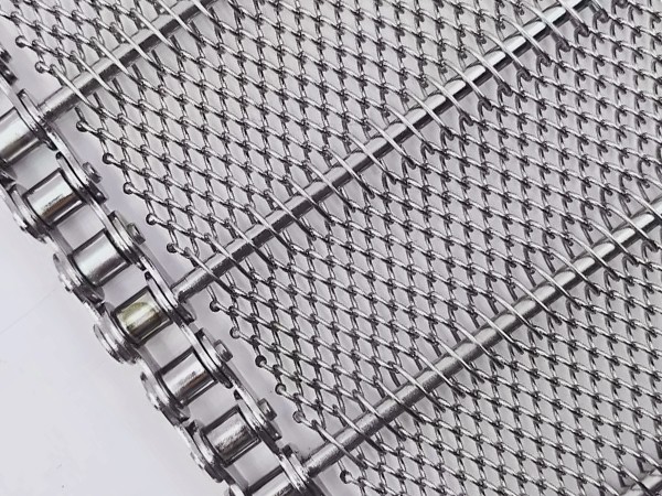
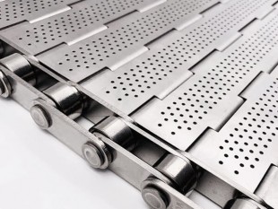
Carrier rods connect the wire mesh to side chains for sprocket-driven operation. Specify the mesh construction, mesh edge and chain assembly separately, including chain pitch, carrier-rod spacing and end fixing.
View dimensions & edge options
|
Read the letters with the correct drawing. The dimension codes are not interchangeable between belt types. In particular, B and C on standard mesh mean different measurements from B and C on rod-reinforced mesh. Dimensions are in millimetres (mm); total belt length is in metres (m).
Mesh Material Availability
Select the wire grade for the conveyed product, cleaning chemicals, operating atmosphere and temperature. The figures below are wire-material reference temperatures; they are not universal continuous-duty ratings for a loaded belt assembly.
|
Material
|
Maximum Wire Operating Temperature °C
|
|
Carbon Steel
|
550
|
|
Galvanised Mild Steel
|
400
|
|
Chrome Molybdenum (3% Chrome)
|
700
|
|
304 Stainless Steel
|
750
|
|
321 Stainless Steel
|
750
|
|
316 Stainless Steel
|
800
|
|
316L Stainless Steel
|
800
|
|
314 Stainless Steel
|
1120
|
|
37/18 Nickel Chrome
|
1120
|
|
80/20 Nickel Chrome
|
1150
|
|
Inconel 600
|
1150
|
|
Inconel 601
|
1150
|
Temperature selection: Confirm actual belt temperature, load, dwell time and heating/cooling cycles. Wire strength decreases at elevated temperatures, and chains, joints or other components may impose lower limits. Grade 314 requires particular review for sustained service around 800–900°C. For galvanised wire, confirm the coating’s suitability for the process and any food-contact or heated duty rather than using 400°C as an automatic approval.
1. Standard Chain Link without Chain Edge Drive
This construction uses interwoven coils without reinforcing cross wires through each mesh connection. Specify the plain mesh edge and the panel arrangement separately. A connector wire between opposite-hand panels does not make the belt a rod-reinforced construction.

Select the drawing to view it at full size.
|
Mark
|
Parameter
|
Unit
|
|
A
|
Lateral coil pitch
|
mm
|
|
B
|
Longitudinal coil pitch
|
mm
|
|
C
|
Wire diameter
|
mm
|
General lateral coil-pitch range: 5.08–25.4 mm. Wire diameter and longitudinal pitch are selected with the application; this range is not a list of approved combinations.
Measuring A and B: where practical, measure across 10 pitches and divide by 10. Record overall belt width, full-loop length and mesh material separately. Include a close-up edge photo when ordering a replacement.
Mesh edge options

Welded Edge (W)
The coil ends are connected by welding at the belt margin. The welded joints form the mesh boundary; this option does not add a side chain or a reinforcing rod.
Selection check: Compare the finished edge profile with the existing belt, especially where it passes guides or comes close to side frames. Supply the required overall width and an edge photograph so the joint position and available clearance can be checked together.
|

Knuckled Edge (K)
The coil ends return into a closed U-shaped connection with the neighbouring coil. The linked wire returns provide an articulated mesh margin without specifying a welded edge joint.
Selection check: Check the outside envelope of the folded returns, not only the width of the central mesh. Identify any nearby guide surfaces and show how the original returns are closed. State this edge code explicitly rather than describing the belt only as a stainless steel mesh.
|
Panel arrangement and panel length

Select the drawing to view it at full size.
The enquiry form allows alternating left-hand/right-hand panels, single-hand mesh, another arrangement, or “not sure”. Identify the construction of the existing belt before assigning a panel pattern.
L — length of alternate-hand mesh panels (mm): record the length of one panel. If the sequence uses unequal lengths, provide a sketch showing each length and the joining locations. L here is not the full-loop belt length and does not have the same meaning as L on the chain-edge drawing.
A wider photograph showing several panel joints is more useful for this check than a close-up of one mesh opening.
Information to include with the enquiry
-
Mesh material/grade; overall width (mm); full-loop length (m).
-
A, B and C; W or K mesh edge; panel arrangement and L where applicable.
-
Conveyed product, operating temperature, belt speed, load, quantity and required delivery.
2. Rod Reinforced Chain Link without Chain Edge Drive
Reinforcing cross wires run through the intermeshing coils. The coil wire and the cross wire are separate components, so both diameters must be specified. The edge option describes how their ends are assembled at the belt margin.

Select the drawing to view it at full size.
|
Mark
|
Parameter
|
Unit
|
|
A
|
Lateral coil pitch
|
mm
|
|
B
|
Coil wire diameter
|
mm
|
|
C
|
Longitudinal cross wire pitch
|
mm
|
|
D
|
Cross wire diameter
|
mm
|
Measuring A and C: measure across 10 pitches where practical and divide by 10. B measures the coil wire; D measures the reinforcing cross wire. Include material/grade, overall width and full-loop length with these four dimensions.
Listed specification examples (mm)
|
A — Lateral coil pitch
|
B — Coil wire diameter
|
C — Cross wire pitch
|
D — Cross wire diameter
|
|
16.93 / 15.24
|
2.03
|
16.93 / 19.05
|
2.64
|
|
16.93 / 15.24
|
2.64
|
16.93 / 19.05
|
2.95
|
|
16.93 / 15.24
|
2.95
|
16.93 / 19.05
|
3.25
|
|
16.93 / 15.24
|
3.25
|
16.93 / 19.05
|
4.06
|
Slash-separated pitches are listed alternatives, not a continuous range or confirmation that every combination is available. Confirm the exact A/C combination and B/D wire pairing on the order drawing. Custom specifications can be reviewed.
Mesh edge options

Welded — In/Out
CLR-W-IN/OUT
Alternating long and short cross rods follow the coil edge, producing staggered welded connections.
Selection check: Check the outermost rod-end position when specifying belt width and side clearance. For a replacement, show several consecutive edge joints so the alternating pattern is visible; a single joint is insufficient to distinguish this arrangement from an in-line edge.
|

Welded — In-line
CLR-W-IN LINE
Equal-length cross rods form an aligned edge; alternate coil ends are compressed before welding.
Selection check: Use the in-line code when this is the required end arrangement. Provide the finished width and show any edge guide contact. Matching the four mesh dimensions alone will not identify whether the rod ends should be staggered or aligned.
|

Welded — Bent pin
CLR-W-BENT PIN
Rod ends turn through 90 degrees and are welded to the preceding coil, with alternate coil ends compressed for alignment.
Selection check: Include a view of the bend as well as the weld. Identify available clearance around the return end and confirm the intended direction of travel on the drawing. Do not substitute this edge solely because its mesh pitch matches an existing straight-ended rod belt.
|

Knuckled — Unwelded tails
CLR-K/U
Paired U-shaped cross wires enter from alternate sides and are retained by knuckled coil ends. The tail ends remain unwelded in the CLR-K/U option.
Selection check: Photograph both belt edges to show the U returns and their insertion pattern. Confirm whether the coil tails are simply closed or additionally welded; the added weld is a separate option and should be stated on the enquiry.
|
Welded knuckled tails
CLR-K/U/W
This is the knuckled construction with the coil tail ends additionally welded.
Selection check: Specify CLR-K/U/W when a welded tail closure is required, and send a close-up showing the weld location. An image of the unwelded CLR-K/U edge should not be treated as an exact approval drawing for this variant.
|
For a different edge, choose “Other / see photo or drawing” on the form. If the edge cannot be identified, select “Not sure” and include clear photos of both sides and the cross-wire ends.
Information to include with the enquiry
-
Coil and cross wire material/grade; overall width (mm); full-loop length (m).
-
A, B, C and D; the complete mesh edge code; photographs of rod ends and coil closures.
-
Product, temperature, belt speed, load, quantity and required delivery.
3. Duplex Rod Reinforced Chain Link without Chain Edge Drive
The duplex construction places twin intermeshing coils at each position with reinforcing cross wires. Confirm the duplex weave itself as well as the dimensions: a single-coil reinforced belt should not be identified as equivalent from pitch and wire diameter alone.

Select the drawing to view it at full size.
|
Mark
|
Parameter
|
Unit
|
|
A
|
Lateral coil pitch
|
mm
|
|
B
|
Coil wire diameter
|
mm
|
|
C
|
Longitudinal cross wire pitch
|
mm
|
|
D
|
Cross wire diameter
|
mm
|
Measuring A and C: use the duplex drawing and average over 10 pitches where practical. State B for the coil wire and D for the cross wire. The coloured coil in the drawing highlights the weave; it does not specify a different material or a coloured coating.
Listed specification examples (mm)
|
A — Lateral coil pitch
|
B — Coil wire diameter
|
C — Cross wire pitch
|
D — Cross wire diameter
|
|
8.47
|
2.03
|
16.93 / 19.05
|
2.64
|
|
8.47
|
2.64
|
16.93 / 19.05
|
2.95
|
|
8.47
|
2.95
|
16.93 / 19.05
|
3.25
|
|
8.47
|
3.25
|
16.93 / 19.05
|
4.06
|
|
5.08
|
2.03
|
10.16
|
2.64
|
Use each row as a listed specification relationship. The 16.93 / 19.05 entries are alternative cross-wire pitches, not a range. Confirm the selected pitch, wire sizes and edge construction together. Custom requirements can be reviewed with a drawing and operating details.
Mesh edge options

Welded
CLR-W-Duplex
Twin-coil tails are welded to equal-length cross wires at the edge.
Selection check: Supply a close-up of the completed edge and confirm overall width at the outermost finished connection. When replacing an existing duplex belt, compare the twin-coil arrangement and the end-joint profile as well as A–D; a generic “welded edge” description is incomplete.
|

Knuckled / Hooked
CLR-K/H-Duplex
Knuckled coil pairs retain hooked cross wires inserted from alternating sides.
Selection check: Show the hook shape on both belt edges and the position of the closed coil returns. Check the available side clearance against the complete hook envelope. Use this full duplex edge code so it is not confused with the U-cross-wire edge of a single-coil reinforced belt.
|
Information to include with the enquiry
-
Coil and cross wire material/grade; overall width (mm); full-loop length (m).
-
A, B, C and D; confirmation of the twin-coil weave; welded or knuckled/hooked edge code.
-
Product, temperature, belt speed, load, quantity and delivery; photos or a drawing for another edge finish.
In this assembly, carrier rods connect the mesh to side chains, and matching sprockets drive the chains. Specify three features separately: the mesh edge, the carrier-rod end fixing and the side-chain construction. A welded mesh edge and a welded washer are different details.

Select the drawing to view it at full size.
|
Mark
|
Parameter
|
Unit
|
|
A
|
Lateral coil pitch
|
mm
|
|
B
|
Coil wire diameter
|
mm
|
|
C
|
Longitudinal coil pitch
|
mm
|
|
E
|
Carrier rod diameter
|
mm
|
|
F
|
Carrier rod pitch
|
mm
|
|
G
|
Chain pitch
|
mm
|
|
H
|
Chain roller diameter
|
mm
|
|
I
|
Inside chain width
|
mm
|
|
J
|
Width between chains / mesh width
|
mm
|
|
K
|
Chain centres
|
mm
|
|
L
|
Overall width
|
mm
|
Drawing notes: A and C refer to the enlarged mesh detail; use G for chain pitch. The source drawing contains a repeated A mark beside the chain, so use the mesh-detail A when completing the form. No D dimension is specified on this drawing. Here C is longitudinal coil pitch, not the reinforcing cross-wire pitch used in Sections 2 and 3. Measure A and C over 10 pitches where practical. Confirm J, K and L separately; if usable mesh width differs from the distance between chains, record both on a sketch.
Mesh edge — the wire-mesh margin
Welded Edge (W)
Select W for the welded coil-edge finish shown in the chain-edge enquiry form. This choice identifies the mesh termination; the carrier-rod retention outside the chain must still be specified.
Selection check: Include the mesh edge and the chain in the same photograph. Confirm how much space is available between the mesh margin, chain plates and any side guards, and state the required mesh width independently of the complete assembly width.
|
Knuckled Edge (K)
Select K for the closed, folded coil returns shown in the form. The linked mesh edge remains a separate feature from the side chain and its rod-end fastener.
Selection check: Show the outer wire returns and their position relative to the carrier rods. Specify whether a larger coil is present at each carrier rod, as requested in the form, rather than assuming the mesh opening is identical throughout the belt.
|
Chain edge — carrier-rod end fixing

Welded washer
A washer is welded to the carrier rod outside the side chain to retain the assembly.
Selection check: Specify the rod-end projection and available side clearance. Treat the welded closure as part of the maintenance plan: if future chain removal is expected, discuss the disassembly method before selecting this fixing.
|

Cotter pin & washer
A washer and cotter pin retain the rod through a hole near its end. The removable fixing can be released for service where access permits.
Selection check: Allow space for the washer, pin and service access. State whether chain or mesh sections must be replaceable on the conveyor, and include a drawing of any nearby side frame that limits removal.
|
Welded nut / other fixing
A welded nut is an additional carrier-rod retention option. Other end fixings can be specified with a photograph or drawing; select “Not sure” on the form if the fixing cannot be identified.
Selection check: For a welded nut, specify the nut and rod-end arrangement on a drawing. For another retention method, send a clear end view and dimensions. Do not infer its geometry or interchangeability from the washer illustrations.
|
Side chains, drive and optional accessories
|
Enquiry item
|
Details to provide
|
|
Materials
|
State mesh/carrier-rod material and chain material separately. Include operating temperature and cleaning or process conditions relevant to material selection.
|
|
Side-chain style
|
Hollow pin, solid pin, other, or not sure. Identify the actual carrier-rod attachment; pin style alone does not establish sprocket compatibility.
|
|
Chain and sprockets
|
Chain pitch G, roller diameter H, inside width I and chain centres K; provide chain and drive-sprocket markings or stamps, plus a photograph or drawing.
|
|
Carrier-rod arrangement
|
Diameter E, spacing F, chosen end fixing and whether a large coil is present at the carrier rod. Show the interface between rod, mesh and chain.
|
|
Edge plates
|
State required height, material and quantity, and provide a drawing or sketch showing the location and attachment.
|
|
Flights
|
Supply a drawing or sketch of the flight shape, dimensions and intended arrangement.
|
|
Duty and supply
|
Full-loop length (m), product, process, minimum and maximum temperature (°C), belt speed, load, quantity, delivery and any special requirements.
|
Match chain pitch, sprockets, carrier rods and the conveyor support arrangement as one assembly. If the mesh is reinforced or duplex, provide that mesh drawing as well as the chain information; do not transfer dimension letters from one form into another without their definitions.
Need help identifying your belt or edge finish?
Send the enquiry form for the correct construction with a full-width belt photo, close-ups of both edges, the applicable dimensions and operating details. Include panel lengths for panelled standard mesh and chain/rod-end details for a chain-driven assembly. If a measurement or edge type is unknown, leave it blank and attach a photograph.
 +86-15369679157